1. Overview
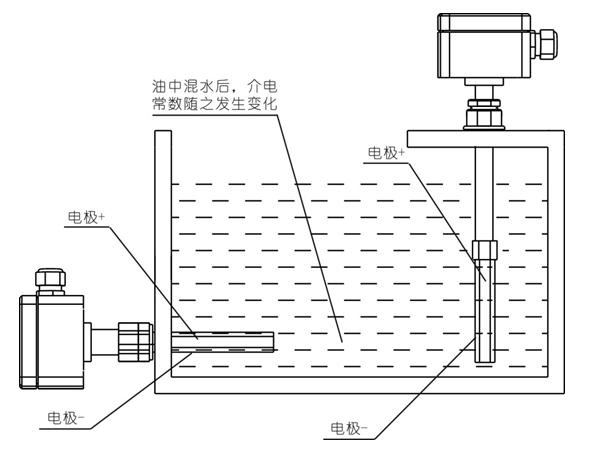
WIM series oil mixed water annunciator can be used to monitor the water content in various oils. It is easy to install and accurate to measure. It can detect that the proportion of water mixed in oil is less than 5%, and it also has an output of one pair of open and close contacts. The controller is divided into side-mounted and top-mounted, and users can choose according to their needs. The oil-mixed water signal device is based on the principle that the capacitance changes with the change of the dielectric constant only when the dielectric constant of the medium between the two plates changes. The controller consists of the probe shell and the inner core to form the capacitor poles. When the oil is mixed with water between the two poles, its dielectric constant will change, which will cause the change of the capacitance value. output contact signal.
2. Main technical parameters
Measuring range: Side mounted: 110mm, Top mounted: 110~3000mm
Operating Voltage: 24VDC, 220VAC/DC
Rated power consumption: 1.5W(24VDC), 3W(220VAC/DC)
Output mode: 1 pair of open and close contacts
Contact capacity: 3A/24VDC, 1A/220VAC/DC
Connection: Thread or Flange
Installation method: side-mounted or top-mounted
Probe Material: Stainless Steel/Brass
Medium temperature: 0~80℃
Environmental conditions: -10~85℃, ≤85%RH, avoid strong corrosive gas
3. Working principle

4. Terminal wiring and structure size

Notice:
① When the water mixing ratio in the oil is greater than the set value, the NO point of the relay is closed, and the NC point is disconnected;
② When the water mixing ratio in the oil is less than the set value, the NO point of the relay is disconnected and the NC point is closed;

5. Installation and commissioning
1. Installation
According to Figure 2, please install as follows:
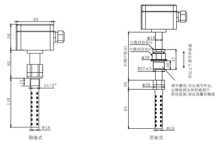
1) Install the controller at the measuring port position through the connecting thread. When installing the top-mounted type, if the probe cannot reach the bottom of the medium to be measured, adjust the adjusting nut shown in Figure 2 to make the probe reach the bottom of the measuring container; If the controller is damaged by friction during rotation, it is necessary to lift the controller up by about 5mm.
2) Open the top cover and connect according to Figure 4.
3) Arrange and fix the outgoing cables, and install the top cover.
Notice:
③ During installation, do not forcefully turn the upper cover by hand to fasten the annunciator, but use a wrench to pull the nut above the connecting thread to fasten it.
④ The controller shall be installed at the side or bottom of the oil tank or oil tank, and the depth of the probe inserted into the oil shall be at least 80mm.
⑤ When connecting the power supply, first check whether the power supply of the product is consistent with the power supply provided locally, and then connect it to prevent burning the controller.
2. Commissioning
The commissioning process of the controller is as follows:
1) Place the pure turbine oil in a container and prepare a cup of clean water (the ratio of clean water to turbine oil is about the set action point ratio).
2) Open the upper cover and you can see two indicator lights (one red and one green) and a potentiometer. The potentiometer clockwise is to increase the proportion of oil mixed with water at the set point, and counterclockwise is to reduce the proportion of oil mixed with water.
3) Connect the wiring according to figure 4, connect the multimeter in the circuit of the opening and closing contact (no and com are connected at both ends of the multimeter respectively), and turn the multimeter to Ohm ("200 Ω" gear).
4) Turn on the power supply of the controller. At this time, the green light of the indicator is on, the red light is off, and the multimeter shows infinite resistance, indicating that the instrument works normally.
5) Mix clean water into the container and stir evenly. Note that the proportion of mixed water should be slightly greater than that of the action point. If the proportion set during the action is 4%, the proportion after mixing water in the oil should be slightly greater than 4%.
6) Insert the controller into the container and turn on the power again.
If the red indicator light is on and the multimeter shows that the resistance tends to zero, it indicates that the relay has acted. At this time
(1) The set point of is less than the required action point. First adjust the potentiometer to make the indicator light green, at the same time, the multimeter shows infinite resistance, and then callback a little to make the red light just on, and the multimeter shows resistance tends to zero.
(2) If the green light is on and the multimeter shows infinite resistance, the relay does not act, and the set point is greater than the required action point. Adjust the potentiometer so that the red light is just on and the multimeter shows that the resistance tends to zero.
Note: the potentiometer rotates counterclockwise to reduce the set value of the action point.
7) After setting, if it is necessary to test the set point again, first cut off the power supply, then clean the controller probe, and then repeat step 6) until the controller reaches the required set point.
8) After adjustment, please cover the upper cover and tighten the fastening screws of the upper cover.
be careful:
① Both positive and negative positions of the potentiometer shall be stopped. During adjustment, it shall rotate slowly to prevent excessive rotation from causing damage to the potentiometer.
② When cleaning the probe, dry it with a dry rag. Do not directly dry the probe with high-temperature electrical appliances such as electric air cylinder, otherwise the sealing material of the probe will be damaged.
③ Every time the annunciator is taken out, the power supply shall be cut off first, and then the annunciator shall be taken out.
④ When connecting the power supply, check the power supply of the product first, and then connect the wires to prevent the controller from being burned out.
6. Precautions
1) When ordering, please note the working voltage, installation method, probe material, ambient temperature, etc.
2) After the goods arrive, the buyer should check whether the original and accessories are complete and intact according to the packing list. If there is any damage, the buyer should contact the supplier as soon as possible.
3) The controller should be stored in a dry, ventilated, cool, non-corrosive gas, well insulated and non-hazardous room. The controller should not be stored in an environment with high temperature and high humidity.
4) When the controller is stored, moved or installed, it should not be dropped to prevent the controller from being damaged.
5) This product is a precision measuring element, and it is strictly forbidden to impact, strongly support or disassemble it at will.
6) Please confirm that the wiring is correct according to the requirements in the manual before powering on.
7) When laying signal cables, please keep a safe distance from high-voltage, high-frequency equipment and cables, so as to avoid interference to the output signal of the controller and induced high voltage damage to the controller.
8) It is strictly forbidden for the user to disassemble or repair the controller by himself, otherwise the warranty will be voided.
9) If the controller does not work normally, please return the controller to our company for inspection.