1. Overview
LSX intelligent flow head efficiency monitor is an intelligent digital instrument that processes standard signals with a single-chip microcomputer as the core. The flow head efficiency monitoring device is formed, and the turbine flow head efficiency monitoring system is formed.
2. Features
The intelligent monitoring device with single-chip microcomputer as the core processor has strong applicability.
Transmitter range, instrument range setting and modification are easy.
With power-off memory and parameter automatic saving function.
It can switch to display instantaneous flow value, working head value, efficiency value and cumulative flow value.
Provide standard 4-20mA output corresponding to instantaneous flow, working head and power.
Perfect system self inspection function.
The transmitter can work (+ 24V).
3、 Technical performance
Display mode: eight digit LED highlighted nixie tube display is clear and intuitive.
Display range: instantaneous flow value: 0-9999.99 m3 / S
Head value: 0-999.99m
Efficiency value: 0-100.00%
Cumulative flow value: 0 ~ 999.99999 KM3 / h
Output signal: 3-way standard 4-20mA output (load resistance ≤ 525 Ω)
Measurement accuracy: ± 0.5% F.S ± 1 word
Working power supply: switching power supply AC85 ~ 265V, dc110 ~ 340v.
Power consumption: 10W.
The instrument provides the transmitter with DC24V power supply, and the transmitter does not need external power supply.
Environmental conditions: temperature: working temperature: 0 ℃ ~ 40 ℃.
Storage temperature: - 25 ℃ ~ + 70 ℃.
Relative humidity: ≤ 85% RH.
4、 Working principle
The flow of the turbine is measured by the volute differential pressure method. According to the relationship between the flow Q and the pressure difference △ P on the inner and outer sides of the volute flow measurement section: q = k √△ P, the flow value of the turbine is calculated. The K value in the formula is the volute flow coefficient. The working head of the turbine is composed of position head, velocity head and pressure head. The pressure head is calculated by measuring the differential pressure between the volute inlet and the draft tube outlet through the differential pressure transmitter, and the speed head can be converted according to the measured turbine flow and the corresponding overflow sectional area. When the instrument is installed, the water head at the position is constant after one-time measurement. The active power n of the generator is converted to 4-20mA by the power transmitter and sent to the instrument.
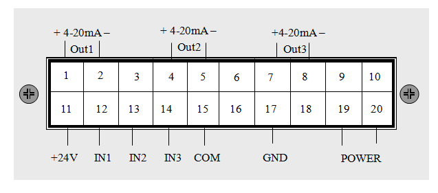
5、 Terminal block

Instrument terminal Description:
Terminals 1 and 2 are instantaneous flow 4-20mA current output
4-5 terminals are working head 4-20mA current output
Terminals 7 and 8 are unit efficiency 4-20mA current output
11 + 24V power supply
12 flow transmitter interface 13 head transmitter interface
14 power transmitter interface 15 transmitter COM interface
17 instrument enclosure ground
19.20 instrument power supply
The connection between the instrument and the differential pressure transmitter can adopt (two-wire system, three wire system and four wire system) to correctly connect according to the different supporting transmitters.
Two-wire connection: transmitter +24V is connected to instrument +24V; transmitter signal output OUT is connected to instrument IN
Three-wire connection: transmitter +24V is connected to instrument +24V; transmitter signal output OUT is connected to instrument IN; transmitter signal output COM is connected to instrument COM
Four-wire connection: Transmitter 24V+ connect instrument +24V; transmitter 24V- connect instrument COM; transmitter signal output OUT+ connect instrument IN; transmitter signal output OUT- connect instrument COM
6. Installation size
The appearance of the instrument and the size of the opening are shown in the following figure:
