1. Overview
The shaft current transformer adopts a hollow annular transformer to monitor the change of the shaft current generated by the large shaft of the hydro-generator set, output the corresponding (1000:1) real-time current value, and collect and display it through a special device.
Please read the manual carefully before use.
This product has the following features:
1. Easy installation, good reliability and anti-interference;
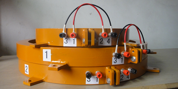
2. The semi-ring structure is adopted, which is easy to install;
2. Main technical performance
Measuring range: 0 ~ 10A
Measurement accuracy: 1.5 class
Output mode: 0 ~ 10mA (AC)
Working winding ratio: 1000/1
Experimental winding ratio: 500/1
Rated frequency: 50Hz
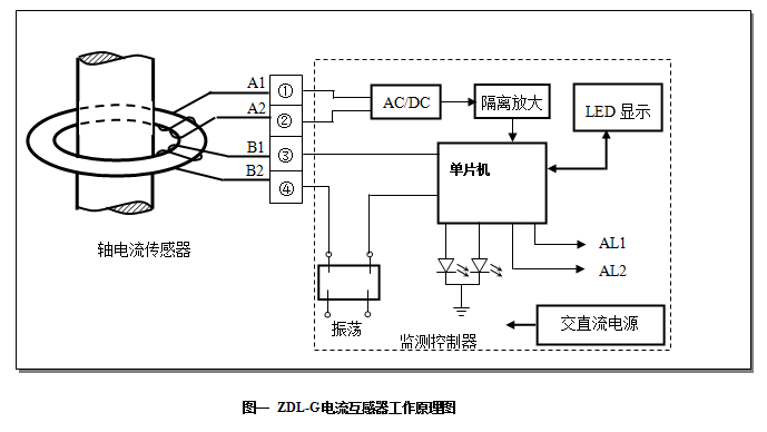
3、 Working principle
4、 Wiring requirements
1. Installation method of current transformer:
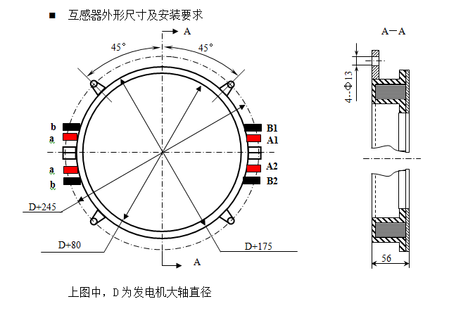
The current transformer shall be installed in the static part that can reflect the large shaft current and fixed with the generator frame through the external support. Before installation, first remove the connecting wire on the transformer and the connecting screw on the connecting plate, then sleeve the two half circular rings on the main shaft of the generator and fix it into a whole circle with screws. The gap at the semi-circular butt joint shall be less than 0.1mm. During installation, the gap between the transformer and the main shaft of the generator shall be as uniform as possible. The fixed transformer shall not be loose.
2. Wiring method of current transformer:
① Two adjacent red terminals (a, a) and two black terminals (B, b) shall be connected
② Connect the two red terminals (A1, A2) at the other end to the A1, A2 of the instrument. Two black terminals (B1 and B2) are connected with B1 and B2 of the instrument
③ After connecting the wiring, check whether the wiring positions of A1, A2, B1 and B2 are correct, which can be judged as follows,
Use the resistance gear of the multimeter to measure that both ends of A1 and A2 are channels, indicating that A1 and A2 are correct; Similarly, measure B1 and B2
Both ends are channels, indicating that B1 and B2 are correct; If there is no connection, it means that the wiring is wrong. Change the wiring sequence until the above two states appear. Then judge A1, A2, B1 and B2. The resistance gear of the multimeter is generally 200 Ω. Measure the resistance at the end of A1 and A2 and write down the resistance; Re measure the resistance at B1 and B2 terminals and record the resistance; Then compare it. If A1 A2 > B1, the resistance at B2 terminal indicates that the wiring is correct. If it is less than A1 A2, the wiring of B1 and B2 is reversed and needs to be replaced.
④ The correct wiring can make the instrument measurement accurate, stable and reliable.
⑤ A1 and A2 are the output AC current of working winding 0-10mA, corresponding to external 0-10a current.
⑥ B1 and B2 are the experimental windings connected to B1 and B2 of the instrument terminal. If there is no monitoring instrument, the wiring can not be unloaded.
It is recommended to use 2.5 square four core shielded cable to connect the terminal A1, A2, B1 and B2 with the instrument, and the specification of the terminal is M5 thread
be careful! When there is no monitoring instrument, the current value can be collected directly at terminals A1 and A2, but not at terminals B1 and B2.