1. Overview
The ZKZ-2T speed monitoring device is a new generation of automatic measurement and control instrument for the unit, which replaces the current speed relay of the hydraulic generator set, and has the functions of dual-channel measurement frequency, unit speed percentage (or actual speed), unit load rejection and overspeed test.
ZKZ-2T speed monitoring device integrates frequency meter, tachometer, speed relay and speed test instrument. Since its measurement and control accuracy is determined by the crystal oscillator, it will not change due to long-term operation, which improves reliability. The measurement and control instrument adopts the hysteresis method to eliminate the jitter of the outlet relay. For the waveform distortion caused by the braking of the unit, the blocking method is adopted to prevent the output from malfunctioning. According to the operation needs of the power plant, the 8 speed outlet values can be easily adjusted on site within a certain range.
The instrument has communication function, and the software has built-in standard MODBUS communication protocol, which can be easily interfaced with the computer, and can be used as an integral part of the computer monitoring system of the whole plant of the hydropower plant.
2. Technical performance
Number of measurement signal channels: two channels, generator PT frequency value or permanent magnet machine Ma frequency.
Measurement frequency range: 0.5~100Hz
Input signal voltage: 0.3~250V
Measurement accuracy: Non-linearity <2%, speed dead zone <0﹒02%
Digital display content: generator speed percentage, generator frequency, output setting value of each channel.
Output contact: J1-J8 can be set by the user within the specified range, and the braking time can be set.
Analog output: 4~20mA (corresponding to the unit speed 0%ne~200%ne)
Communication content: 1-way analog and 8-way switch
Output contact capacity: 0.3A/220VDC, 1A/30VDC
Permanent magnet machine frequency: Permanent magnet machine center frequency, standard: 50Hz
Working Environment: Temperature 0~50℃ Humidity<85%
Dimensions: 160 x 80 x 250mm on a plate
Power supply: AC85-265V or DC120-340V
3. Panel description

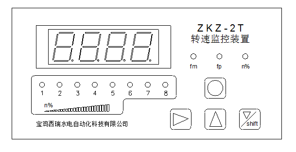
1. The fp light is on: the displayed value is the frequency measured by the PT input signal; the fm light is on: the frequency is measured by the permanent magnet machine (Ma) input signal; the n% light is on: the displayed value is the speed percentage.
2. J1-J8 relay alarm output indicator light.
4. Terminals

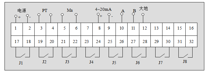
Power supply: Terminals 1 and 2, regardless of positive and negative poles.
PT signal: Terminals 3 and 4.
Ma signal: Terminals 5 and 6.
4-20mA output: 8 (current positive), 9 (current negative).
Communication: 10(A), 11(B).
Ground: 12 (Case Ground)
Relay output: Terminals 17 to 32
5. Installation size
The appearance of the instrument and the size of the opening are shown in the following figure:
