1. Overview
The shaft current monitoring device uses a high-performance single-chip microcomputer as the core control component to form a controller, and uses a hollow annular transformer as the shaft current sensor to monitor the change of the shaft current generated by the large shaft of the hydro-generator set. The single-chip microcomputer monitors the change value of the shaft current sensor in real time. This value has a linear relationship with the large shaft current. After filtering and numerical transformation processing, after confirming that the shaft current exceeds the set value, the shaft current monitoring device outputs a secondary alarm signal. The device adopts four-digit seven-segment LED as the display unit, and the parameter setting and real-time display are clear and intuitive.
2. Features
With high-performance single-chip microcomputer as the core control component, it has good reliability and anti-interference;
The use of special acquisition chip makes the display more stable and reliable, with high accuracy.
The single-chip microcomputer can process the numerical value intelligently, the 2-level alarm contact output, and the setting value of the alarm contact can be arbitrarily set within the range, which is flexible and convenient to use;
The second-level alarm can set the delay according to user needs.
With standard MODBUS 485 communication.
AC and DC power supply system.
The shaft current sensor adopts a split-half ring structure, which is easy to install;
Using high-brightness LED as the man-machine interface, the shaft current parameter value and device status are clear and intuitive
3. Technical performance
Measuring range: 0 ~ 5A/10A Overcurrent capability: 10A
Measurement accuracy: <1.5%
Digital display mode: LED display
Output signal: 2 groups of relay contact output Alarm mode: upper limit alarm
Contact capacity: 7A/AC250V 7A/DC30V (resistive load)
Contact form: DPDT
Use environment: ambient temperature 0 ~ 50 ℃ relative humidity <95%
Power supply voltage: AC 90-260V switching power supply
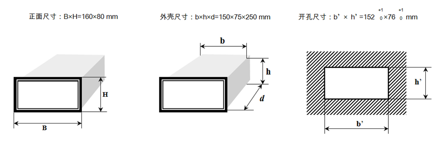
Dimensions: Plate: W×H×D = 160×80×250
Power supply: AC/DC 220V/50Hz
4. Panel description
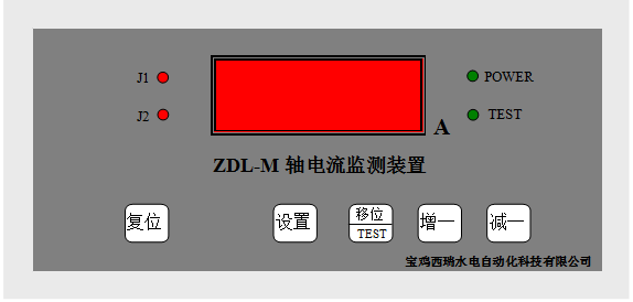
1. Four-digit LED digital tube display window, showing running and setting parameters.
2. The nature indicator light, POWER is on, indicating that the device is powered on. J1 is on, indicating the first-level alarm action. J2 is on, indicating the secondary alarm action. TSET is on, indicating that the test is being performed.
3. In the key area, the sequence is → reset, setting, shift/test, plus one, minus one.
5. Terminals
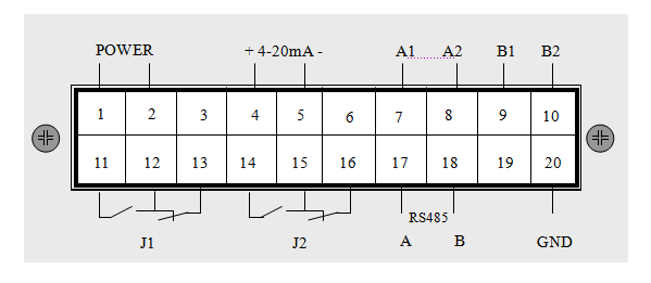
1. POWER is the power supply.
2. A1 and A2 are working windings
3. B1 and B2 are test windings
6. Installation size
7. Current sensor size and installation
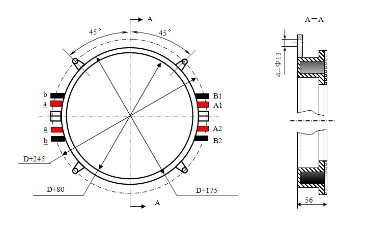
In the above picture, D is the diameter of the generator shaft
The shaft current sensor should be installed in the static part that can reflect the large shaft current, and fixed to the generator frame through the external support. Before installation, first remove the connecting wire on the sensor and the screw on the connecting plate, then put the two halves of the ring on the big shaft of the generator, and fix it into a whole circle with screws. The gap at the butt joint of the semicircle should be less than 0.1mm. During installation, the gap between the sensor and the generator shaft should be as uniform as possible. The fixed sensor is not allowed to loosen.